how to drawing pencil 3d
How to Plough Your 3D Printer into a Plotter in I Hour
Teach Your 3D Printer How to Draw and Write on Paper with Pens, Color Pencils, Crayons and More! 🖍
Edifice a plotter was on my list for a long fourth dimension. A plotter is a device that tin draw text and pictures on paper using a pen. A few weeks ago, after beau Israeli makers built a pocket-size plotter from former CD drives, I decided information technology was finally time to build my ain plotter.
I sabbatum down and started planning the hardware, when I suddenly realized that there might be a nice shortcut — my 3D printer already includes all the hardware and electronics I need, I just need to figure out how to attach a pen to it and how to tell information technology to depict.
I 60 minutes afterward I had a working epitome. It was much easier than I initially expected. In this weblog post y'all volition learn how yous can make your own printer draw.
Turning a 3D Printer into a second Printer 🖨
Y'all might be wondering what is the utility in turning a 3D printer into something that tin draw second pictures on a paper. Later on all, conventional printers do that for several decades already, isn't that a step astern?
Commencement, who said everything I brand has to exist useful?
Second, a plotter allows you lot to draw with pen, colored pencils, crayons, markers, and even a quill. Basically everything that can leave marks on a piece of paper. You even draw on dissimilar materials, such as cardboard or glass. You can likewise get creative with unique ink types, such as golden, silver or glow-in-the-night —you proper noun it.
Step 1 — Attaching a Pen
You want to reliably mount a pen to your printer'due south head and ensure that the tip of the pen goes a little beneath the nozzle. I started by designing a small part of this purpose. Information technology clips to the printer'south head, and I use a pocket-size M3 spiral to fix the pen to information technology:
You tin get the model here. It should fit any Creality Ender-three or CR-20 printer, and possibly other Creality printers. It is also customizable, so you can tinker with the dimensions (if you want to fit a larger marking, or demand a tighter fit with the printer).
For other printers, you will need to design your own mounting mechanism (when you do, please share a link in the comments). While is it also possible to utilise screws for mounting the pen, I personally prefer the clipping mechanism as it allows me to switch betwixt 3D printer and plotter modes really apace, and also change pens actually quick.
Step 2 — Calibration
One time y'all take successfully mounted your pen to your printer, information technology'southward time to calibrate information technology. You volition need to attach a slice of paper to your printer's bed:
Next, you will demand to find the right tiptop for printing. I recommend using Repetier Host for this (I initially started with Cura, only Repetier Host made everything much easier, so I will stick with information technology for this tutorial).
Before starting, make sure your printer's bed is level and that both the nozzle and the printer bed are absurd.
Afterward homing your printer, become to the "Manual Control" tab inside Repetier, and movement the print head up until the tip of the pen goes above the paper. And then, move your X / Y axis to the edge of where you want your drawing to exist. Finally, move the Z axis down in 0.1mm increments, until you see the tip of the pen touching the paper. You tin and so move the X/Y a little and check that the pen actually leaves a trace on the paper. When done, notation the X/Y/Z values that announced in the top line:
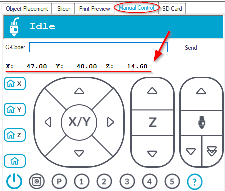
In my case, the values were 47 for X, forty for Y and fourteen.6 for Z. We will use these values soon when we generate the GCode file for printing.
Step iii— Choosing a what to print
That's a tough ane. So many options. You volition need to become it in vector format, though — so if yous utilise Google Images, add together the text type:svg at the end of your search query. You can also convert JPEG and PNG images to SVG, but I'd advise to start with something that already comes as a vector to make things elementary.
Pace 4 — Generating GCode
When I started this projection, I idea I was going to spend some hours on getting the hardware correct. I was surprised how quickly I got the hardware role working. The software was, however, a completely different story — every bit always, software is where the real complexity lies.
Later spending several hours on research, I finally found a workflow that works pretty reliably, though, it requires some setup. Other than Repetier Host mentioned higher up, you lot also need to get Inkscape (which is, past the way, also useful if you want to create PCB art!).
Inside Inkscape, create a new file and become to File carte → Document Properties (Shortcut: Ctrl+Shift+D). And then set the document size a little smaller than your print bed size, and likewise make certain you lot employ mm for the units.

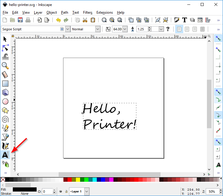
One time yous have gear up the size, yous can import any SVG file that you like, or simply draw some text using the Text tool:
When done, with the text yet selected, click on Path menu → Object to Path (Shift+Ctrl+C). This will convert the text into a series of points continued by lines, which is required for feeding into the printer. You can add more elements such as spirals and star shapes, repeating the "Object to Path" operation for each:
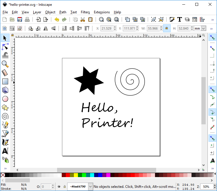
When printing, objects won't exist filled, so you may want to remove their fill up color and set their stroke color to black (or whatever colour your pen is), then you get a more authentic representation of the last result. Select all the objects (Ctrl+A) and and then remove the fill and apply black color for stroke (Ctrl+Shift+F):

When yous are happy with the consequence, it is time to generate the GCode for the printer! Nosotros volition use an extension called "Gcodetools", which comes bundled with Inkscape (if not, yous accept an older version and need to upgrade).
We will offset by defining the Orientation Points, which tell the printer how to map the lines on screen onto the paper. Go to Extensions Carte du jour → Gcodetools → Orientation Points… and afterwards making sure "2-betoken" mode is selected click Apply and so Close. You lot should at present run into 2 new text elements added at the bottom of your drawing:
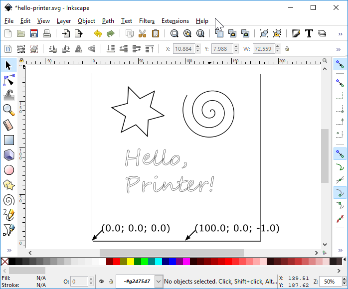
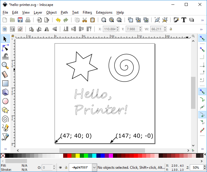
These are the Orientation Points. Each point is a list of 10, Y, Z coordinates that specifies the target location of that point in the Printer'south coordinate organization. You need to edit them to match the X / Y yous establish in the scale pace, and set the Z (the tertiary coordinate) to 0.
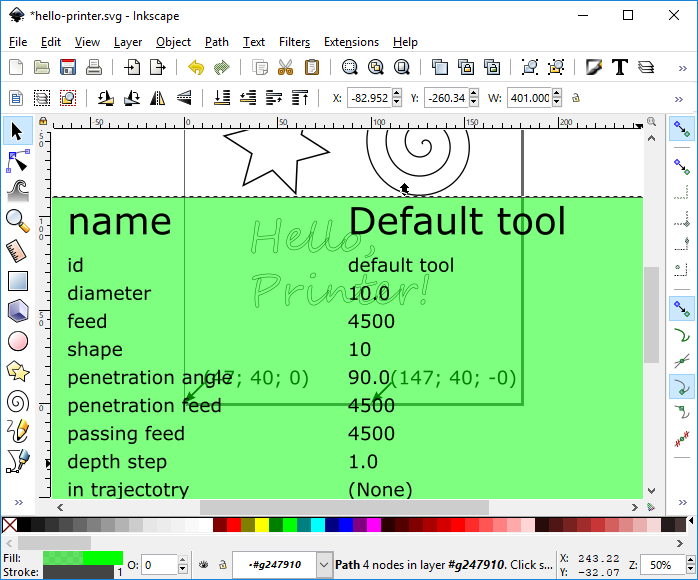
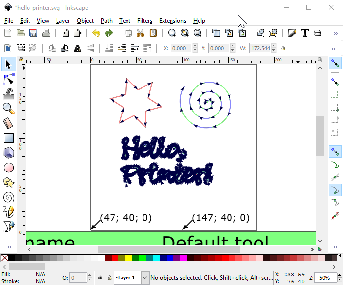
Edit the text on the left betoken and update it to comprise the 10 / Y coordinates that you lot constitute. In my instance, it was (47; 40; 0). For the right bespeak, add 100 to the Ten value, copy the Y/Z from the first one, e.m. (147; 40; 0):
Next, nosotros demand to generate a tool and configure its speed. This pace is optional, but if y'all don't practise this, your printer will draw actually really tedious. Go to Extensions carte du jour → Gcodetools → Tools Library…, and select "default" in "Tool types":
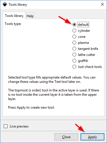
Click Apply then Shut, and you should see a light-green rectangle with a lot of settings added to your drawing:
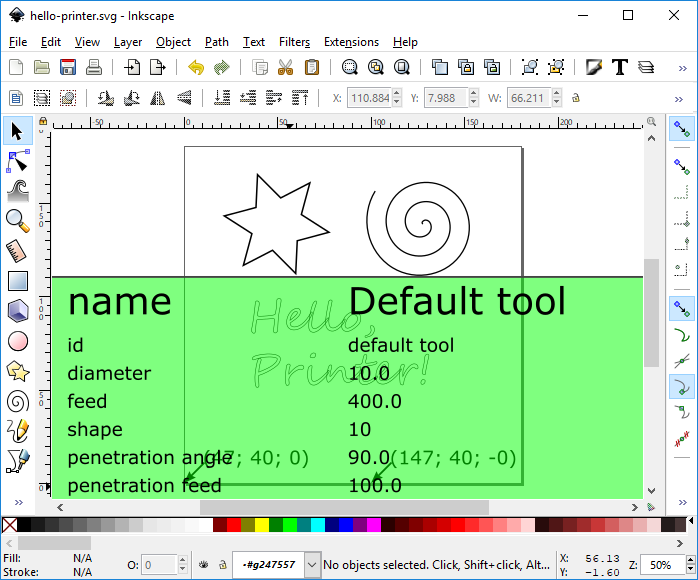
You lot tin move this rectangle away (together with all the values) and then it doesn't come over your drawing. Then, yous want to edit the text and change the values for "Feed", "Penetration Feed", "Passing Feed" to gear up the movement speed of the printer when drawing. I use 4500 for all of them (the unit is mm/min, so this value corresponds to 75 mm/sec).
We are finally fix to generate the GCode! Select all the elements in your cartoon (Ctrl+A), and get to Extensions → Gcodetools → Path to Gcode…
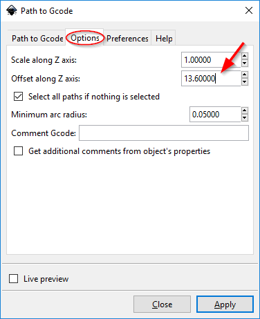
In that location, go to the Options tab, and set "Scale forth Z axis" to i, and "Starting time along Z axis" to the Z value that you found in the calibration step, minus 1 (I found fourteen.6, so I set information technology here to 13.6):
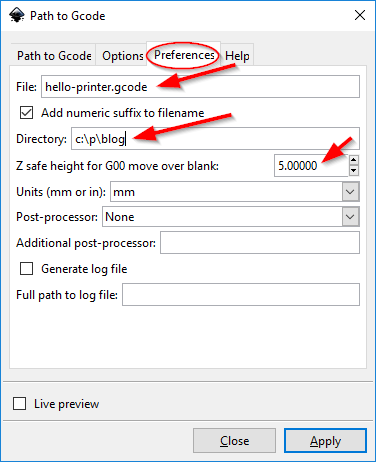
Next, become to the Preferences tab, and set the name of the output file and the path of the directory when you desire it to be saved. You can likewise set the Z safe height to a lower value, to speed up the print (I use five):
Finally, switch to the Path to Gcode tab, set the Depth Function to 1 and click Utilise. It will take a few seconds and might spit a warning about no paths selected which yous can safely ignore. You should see a new layer on elevation of your cartoon, showing the moves of the print-head in the generated Gcode file:
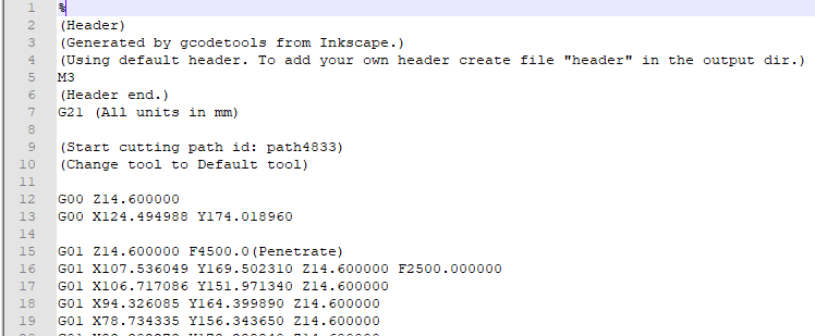
At this point, I advise opening the .gcode file in a text editor and verifying that the information technology looks legit — particularly that the Z values at that place match the calibration value that yous establish:
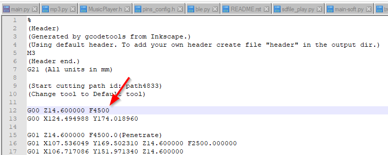
I too suggest editing the showtime G00 line and adding F4500 at the end, otherwise, your printer might make the initial caput movement really slow:
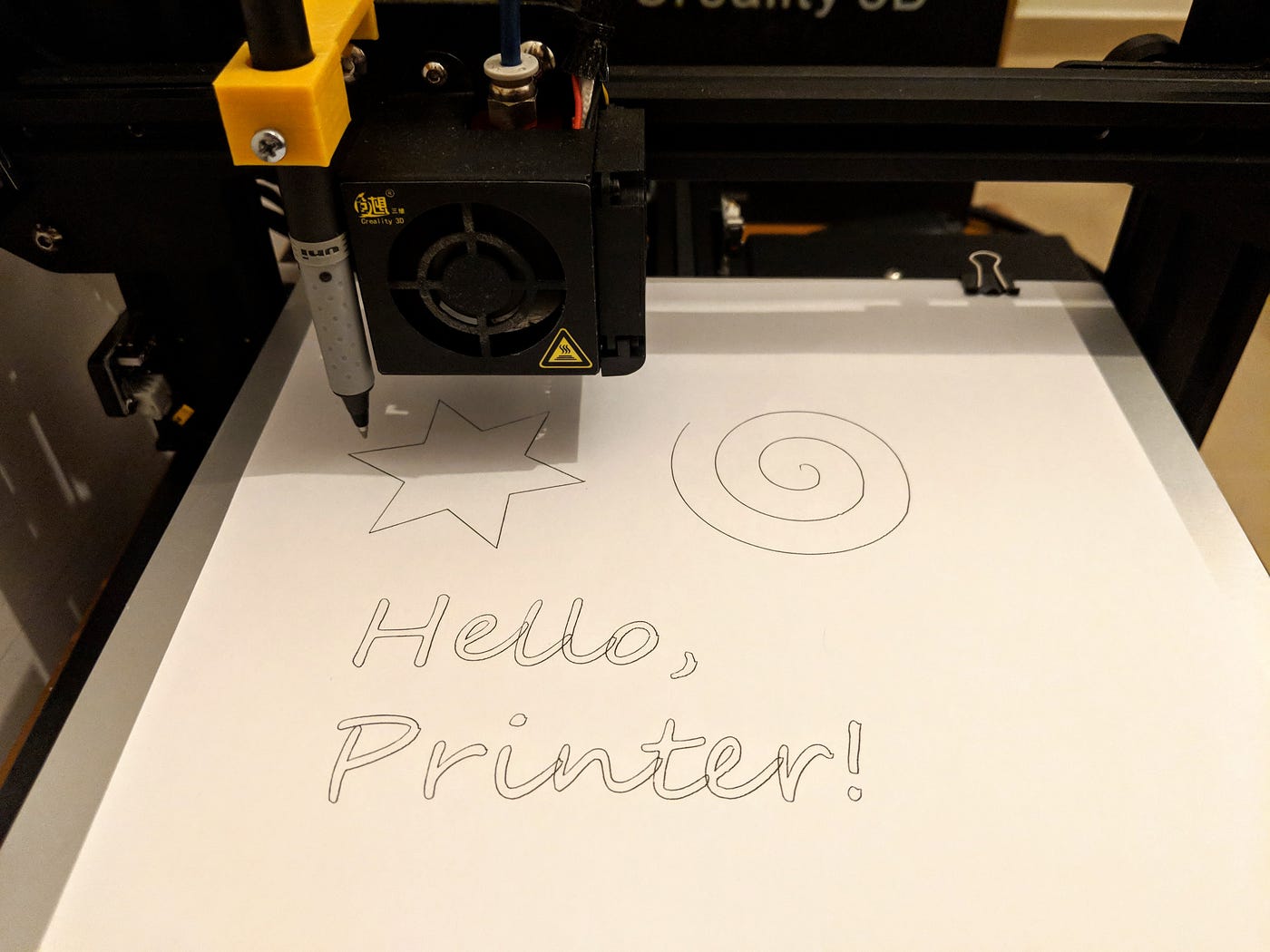
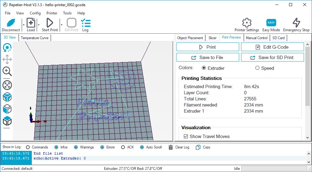
That's information technology! You are ready to print. Load your Gcode file in Repetier host, and you should run across your cartoon on the screen:
Say your prayer, click the "Start Impress" button and… enjoy the bear witness!
Congratulations! 🎉
Your 3D printer now besides doubles equally a plotter. Yous can have it 1 step further and experiment with the different settings of Gcodetools — for example, you can configure it to change the height of the pen according to the colour of the line, thus making the plotter draw thinner/thicker lines. You tin also use the "Expanse" function to make full shapes instead of merely cartoon the outline. ⭐
Please keep experimenting and try unlike types of pens and materials, and post you results in the comments — I'd dearest to run into how far you can accept this!
This is my 5th mail service in my Postober challenge — writing something new every single solar day throughout October.
I will tweet whenever I publish a new post, hope! ✍
Source: https://urish.medium.com/how-to-turn-your-3d-printer-into-a-plotter-in-one-hour-d6fe14559f1a
Post a Comment for "how to drawing pencil 3d"